Ethernet is currently undergoing extensive standardization toward carrier-grade enhancement. This drive started early in the current decade, when it became clear that native Ethernet switches faced significant scalability problems if employed within telecommunication service provider networks. The development of Provider Bridges (PBs) and Provider Backbone Bridges (PBBs) is therefore part of a gradual extension of switch functionalities toward the major carrier-grade goal of scalability.
Native Ethernet Switching and VLAN-Switched Networks
Ethernet switches and bridges started out as layer-2 devices connecting different LANs. Typically hardware-based, switches have a Medium Access Control (MAC) layer at each port. They build and maintain a source address table (SAT) associating the source addresses of incoming frames to their corresponding ports, a process called learning. If the destination address of an outgoing frame is not on its SAT, a switch acts like a layer-1 repeater by sending a copy of the frame to all output ports. This is called flooding.
A VLAN is essentially a logical partition of the network. VLANs were introduced to split the LAN’s broadcast domain. In 1998, the
IEEE 802.1Q standard introduced the Q-tag, a new frame field that includes an explicit 12-bit VLAN identifier (VLAN ID).
In early provider deployment of native Ethernet switches, VLANs were seen by them as the natural way to differentiate customer networks while maintaining a cheap end-to-end Ethernet infrastructure. In this setting, service providers assign a unique 12-bit VLAN ID (VID) field within the Q-tag to each customer network. VLAN switches add the Q-tag at the ingress node and remove it at the egress node.
This use of VLANs quickly ran into scalability issues. The VID’s 12 bits limited the number of supported customers to a maximum of 4094 (excluding reserved VIDs “0” and “4095”). In addition, the customers required the same VID field to partition and manage their own networks, leading to further customer-provider interoperability issues.
Provider Bridge and Provider Backbone Bridge
The step-by-step evolution toward carrier-grade architectures implied the introduction of further hierarchical layer-2 sub-layers. In turn, PBs (
IEEE 802.1ad, 2005) and PBBs (IEEE 802.1ah, 2008) were developed. Through tagging and encapsulation, the original
IEEE 802.3 Ethernet frame shown in Fig. 1 (a) underwent a consequent evolution aimed at preserving its structure for backward compatibility (see Fig. 1).
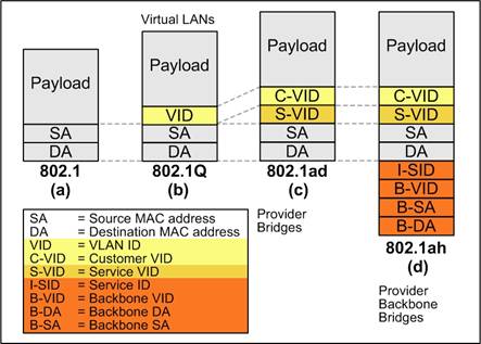
Fig. 1. Ethernet frame evolution
In an effort to mitigate provider scalability problems, the VLAN plane was split by introducing an additional Q-tag, represented in Fig. 1 (c) by its VID field. This resulted in two separate VID fields specifically destined to be used by customers (C-VID) and service providers (S-VID). The essential feature of PBs, the VLAN stacking of two Q-tags, was introduced in the
802.1ad standard and is often referred to as Q-in-Q.
In spite of PBs controlling their own S-VID, there were still scalability issues unresolved by 802.1ad. First, PBs were still required to learn all attached customer destination addresses (DAs), resulting in potential SAT overflows and broadcast storms. Second, control frames were unrestricted to the provider or customer domains. Since it was originally designed for enterprise LAN applications, the 12-bit S-VID was still insufficient to perform two key functions simultaneously: the identification of customer service instances and forwarding within the provider network.
The 802.1ah standard draft introduces yet another hierarchical sub-layer, this time by means of encapsulation of the customer frame within a provider frame. PBBs act as backbone edge switches that append their own source address (B-SA) and destination address (B-DA), as well as a backbone VID (B-VID). A new 24-bit field called the service ID (I-SID) is also introduced to identify a customer-specific service instance (see Fig. 1 (d)).
PBBs complete the separation between customer and provider domains by duplicating the MAC layer, hence the term MAC-in-MAC. In addition, PBBs allow for up to 16 million service instances to be defined (I-SID) without affecting the forwarding fields (B-VID, B-SA, and B-DA).
Further reading
- Special Issue on Carrier-Class Ethernet, IEEE Communications Magazine, vol. 46, no. 9, Sept. 2008.
- D. Allan, N. Bragg, A. McGuire, and A. Reid, “Ethernet as Carrier Transport Infrastructure,” IEEE Communications Magazine, vol. 44, no. 2, pp. 134–140, Feb. 2006.
|